The harbor always included two main zones: water zone and land zone.
· Water zones call pond of harbor, where has arranged many routes for vessels at pond of harbor, embankment/dike prevent sand – reducing power of wave, gate of harbor, routes of vessels egress/ingress with navigation signals and reverse area of vessels, waiting zone of vessels, etc.
· Water zone divides outside water zone and inside water zone. Outside water zone is sea area adjacent outside water zone where has natural sea bedding doesn’t enough deep and area to use mooring the vessels waiting to ingress the harbor. Inside water zone is area with embankment/dike to prevent wave, the inside water zone include:
1. Inside the water zone mooring vessels waiting ingress to harbor and in same cases the mooring vessel can be bypass stevedore at side of vessels or waiting to ingress the harbor.
2. In front harbor is pond to mooring vessel ingress harbor and do stevedore work to harbor.
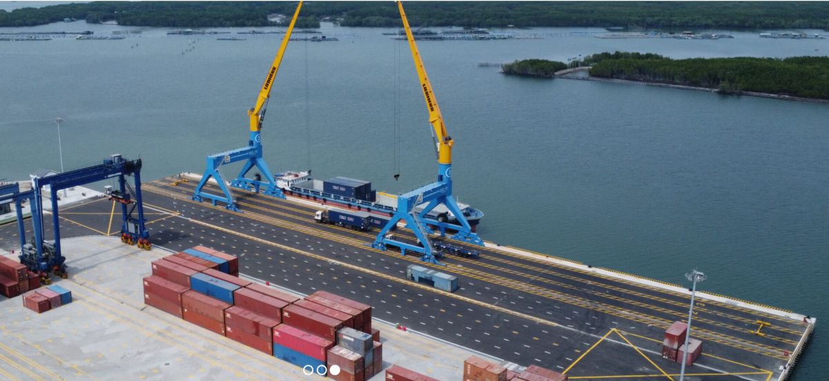
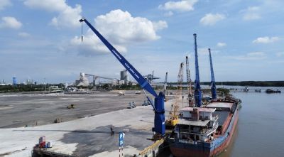
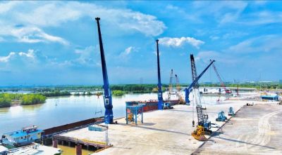
· Adjacent to outline of harbor is a land (called harbor’s land) where is arranged equipment, mobile crane, or fixed crane, warehouses, maintenance factory, internal road, and facility buildings. The harbor land divides two areas front area and rear area.
o The front area is called the buffet area, where is most important area located adjacent to the edge of harbor, this area is arranged fixed crane, mobile crane, truck roads and warehouses or yards and other buildings, equipment to be sure of working for the goods, commodities, etc. safety and effective.
o The rear area is arranged warehouses, second area of yards, equipment for warehouses/ yards, production areas, office buildings for customs, tariffs, border, quarantine, etc. other buildings for daily working at harbor/ port, railway, traffic roads, facility buildings for electric and water supply, wastewater treatment, tele-communication, etc.
· Besides, the most important is routes of vessels from harbor to sea routes to ingress/ egress conveniently with the railway, traffic roads to deliver the goods, commodity.

Lien Chieu port – Danang city

Hai Phong port

1. Embankment/dikes. 2. Conduct channel. 3. Water Pond of port.
4. Water in front of port. 5. Exposing of port. 6. Adjacent of port.
7. Warehouses. 8. Railways of port.
9. Railway station. 10. Damp prevent waves
Arrangement for harbor’s land
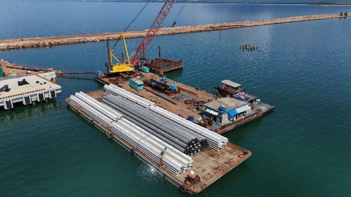
The general merchandise area has functioned for stevedore the commodities: packages, steel and equipment inside container multi-function or single-function, super weighting, super-size, etc.
These jetties have the same technology or similar to be arranged by group.
The same of development of transportation and stevedore for a model of the general merchandise area to be arranged specialty as below:
· Container jetty area.
· Stevedore for package area need to have shelter.
· Stevedore for the general merchandise area without shelter.
· Stevedore for commodity area to arrange along yard.
· Transport area lighter.
· The fragile commodity area.
· The special commodity area (the dangerous commodity)

Tuas port – Singapore
The arrangement for general merchandise area on master layout must be considered the information hereunder:
- Allow to arrange adjacent with the tenant area, wooden commodity area, general services for bypass vessel teams and technical support boat teams.
- Doesn’t allow to arrange adjacent at bulk yard (except the case private jetty has warehouse).
- Consider the traffic issues from the general merchandise harbor to nation traffic systems such as railway, roads.
- These jetties don’t have the same function at general merchandise harbor need to be consider the shifting zone together.
- These jetties can be arranged nearby container yard with the general merchandise harbor to store on yard (there is no shelter) and stevedore can be arranged horizontal of harbor.
· Arrangement according to technical requirement of stevedoring should be located doesn’t access 4 jetties at the same harbor.
· To design the exposing jetty for general merchandise should be used at two both sides to stevedore as same technical diagram.
· The length of exposing jetty to be determine as sum of 3 to 4 jetties for the mooring of each side.
· To select the shape of width’s expose jetty should be consider for some information as hereunder:
· Potential to arrange railway to harbor.
· Comply with the dimensions and shape requirements of the in front pond of exposing jetty.
· Consideration of arrangement for two ends of exposing jetty.
· Distance from edge to central of nearest crane railways must be complied with safety distance requirement for boom’s crane, vessel to have positive for working.
· The quantity of crane’s railways of general merchandise port/ harbor to be determine as technical of harbor specification.

The land yard behind port.

Dinh Vu port
Container yard
· Container yard for the receiving, storing in short term and move to other transportation, these containers to approach by sea water way and reserve.
· The selection of mechanization for stevedore and this arrangement depends on calculation for quantity of container and transportation services (transport “from door to door”, move out apart of commodity inside of container or move out whole, etc.)
· The container jetty includes the front yard; the back yard includes functioning areas and stevedore from transportation to vehicles of railway and road for transportations.
· Yard to receiving of container from vehicles, category containers must be move immediately or short-term storage at yard.
· Warehouse CFS to storage/ move out commodity or whole of container.
· These facilities are buildings: garage, preparation shelter, scale station, operation building to services.
· These buildings to operation: control centre, IT centre, Tele-communication, etc.
· The front buildings include cranes on railways to stevedore for vessels and moving containers from yard to jetty and reserve.
· The back buildings include yard area and stevedore systems from vehicles by railways or roads.
Water area of port/ harbor/jetty:

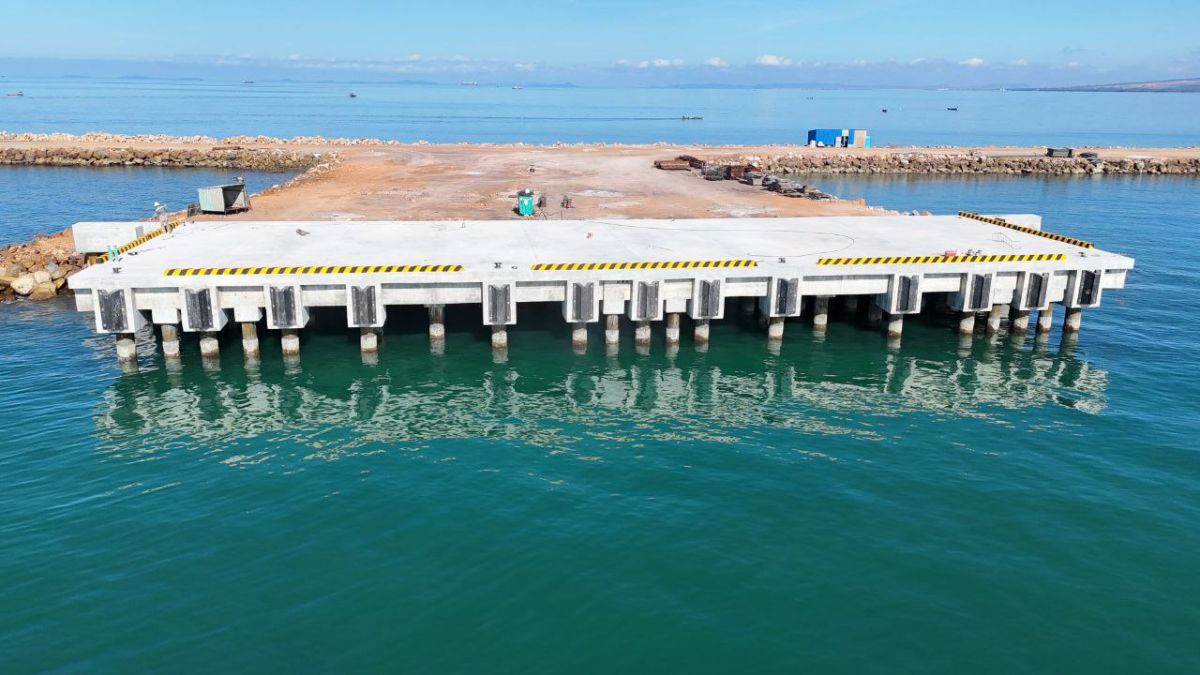
Vung tau port – BRVT province
The main items of water area of port/ harbor/ jetty
The principle of the front water of port/ harbor/jetty is the wider is the better it is convenient to transport. However, it is regarding investment fee and individual waves in the pond of harbor to be interrupt the stevedore and operation of technical boats as well as it to create wave load, tidal load to impact for mooring vessels and port/ harbor.
The dimensions of the front pond and width of port’s gate to be determine for long-life of port.
Master plan design need to be considered the solution for maintenance of pond doesn’t to be damaged by wave/ tidal, vessels ingress/egress must be saved at exposing port and inside port.
Area of water pond includes:
- External routes.
- Turning area for vessel – the water area inside of port where is adjacent to gate of turning vessels before approach to port or move out port.
- The pilot tugboat guilds the vessel to tie/un-tie rope, to mooring at port/ or along ship of cargo vessel.
- Internal route to connect other zones.
- Mooring zone – where the place for vessels to wait ingress to port receiving/stevedore commodity and other purposes.
- Mooring zone to stevedore commodity by along ship.
- Location to treat diesel/ lubricant leaking to sea in port.
These basic elements of the front pond suggest do not combine in order to separate zone can used correct itself functions.
In the water pond of port is necessary to have water pond for technical boats of port, water vehicles as canoes of custom, border, quarantine and other authorities.
The gate to egress/ ingress of port
The gate of port is combine of technical issues to ensure for each vessel egress/ingress are includes: gate of port, guildance route to arrange vessels nearby gate and turning area, its means all segments impact safety and time to move vessels ingress/ egress.
Gate to entrance port is distance of 2 ends of embankment/dike.
In case doesn’t embankments/ dikes can be towaged two vessels at the same time ingress/ egress with the depth of water pond is calculated enough deep, the wide enough width, specially in this case the route of port is two ways.
The formular to calculate width of port’s gate according to the length of perpendicular with central line of route to port at calculated depth. The width of port’s gate to ingress/egress by formular:
Bn = Bc + (vd/v)Lc + vtpsinβ + ∆B (3 – 1)
Bc – the width of vessel calculated;
Lc – the longest of vessel calculated;
tp – time to turning of vessel (calculate by each 60 second);
β – the angle to turn vessel;
∆B – the provisional width to prevent clashing between vessels to embankment/ dike or slope.
The width of port’s gate calculate at formular (3-1) doesn’t less than 0,8Lc.
The maximum for width of port’s gate to determine by the ensure water pond doesn’t impact by wave forces. Depends on particular conditions of each port and based on the results of study for model.
Turning area
The turning area must be have enough dimensions and shape on layout plan to do all activities by neccesseries manner to conduct vessel ingress/ egress, specially must be ensure:
- Ability for reducing power of vessel to approach port.
- Ability for turning by itself with an opening angle as requirement on circle.
- Ability to mooring and temporary anchorage in same incident case.
These requirements above must be ensure in same cases below:
- The diameter of turning area doesn’t less than 3,5Lc.
- Distance of straight line of main ingress from port’s gate doesn’t less than 3,5Lc.

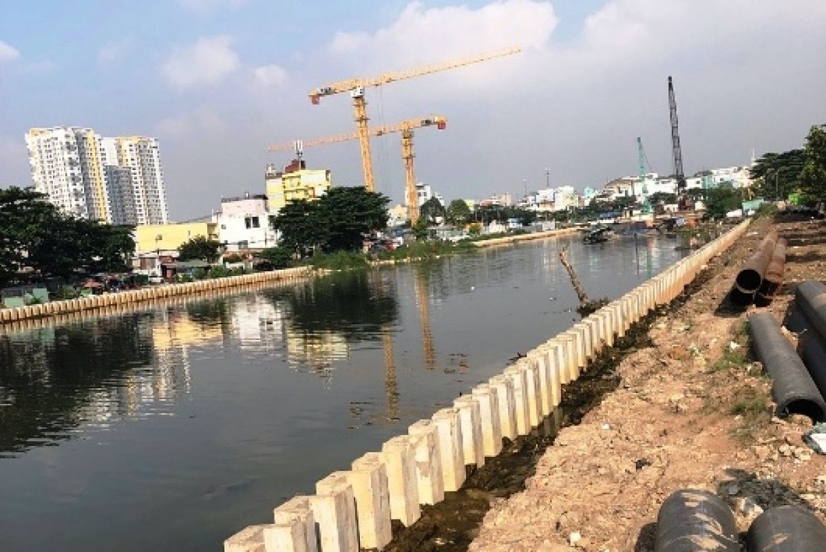
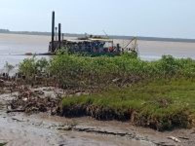
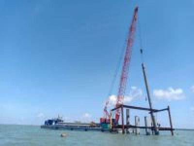
Dikes – Thermo Power Duyên Hải – Trà Vinh province
The arrangement on layout must be have the center line of route at tangent line or the line cut at circle of turning pond.
The minimum distance of straight line from gate’s port can be ascending to 4,5Lc it can be consider the manner characteric of vessel ingress and weather conditions – hydrological conditions at construction location.
However, it can be adjusted as below. The turning area can be arranged a half of circle with radius doesn’t less than 2,5Lc. The position of curve line’s half circle to be arranged provided central line of vessel’s route has intersection at middle of curve line of circle.

Within the mass vessel ingress to port must be arranged tugboats therefore the diameter of turning water pond to be determine as formular:
D = 1,25Lc +150m
But it doesn’t less than D = 2Lc.
In whole of turning pond must have equal of calculation depth and doesn’t overlap with the mooring pond area, anchorage pond area and mission pond area.
The mission pond area
- Dimensions of mission pond area to be determined by the ensurance distences and convenient in the process ingress to port, mooring and stevedore as well as to consider the new invest for mass size vessel in the future.
- Depends on the ability of turning of vessel the water turning pond can be have two categories as below:
o The narrow pond doesn’t allow for turning vessels.
o The enough space for turning vessels.
The mooring pond area and stevedore
The mooring pond area and stevedore can be located at the front water pond and internal water pond.
The requirements of the front mooring pond:
· The location to mooring and conduct channel for the vessels to ensure the safety and convenient for vessels in during fulltime period at port.
· The depth must be enough for vessels to mooring and turning when to have high wave and lowest water of tidal.
· The water pond area must be enough quantity calculated ships to mooring.
· The geological of mooring pond must be firmed to anchorage.
· The best option for mooring water pond should be protected by natural topography of wind, wave to impact the vessels where have covered wave tight and there is not strong flow (speed of flow is over 1,5 m/s).
· The external mooring water pond to arrange nearby at port’s gate however it’s considered where doesn’t interrupt other vessels ingress/egress to port. On the master plan must be indicated number or signals.
· The water mooring pond is located the vessels to line up for waiting of weather conditions or other reasons.
· Dimensions of water mooring pond to be determine depends on method of mooring and quantiy of port to mooring.
The selection of mooring method need to consider these items below:
1. The external water mooring pond has enough area should be selected the anchored because it has more positive compare with other method.
2. The mooring vessel to 2 bouys or 2 pilecaps to be applied for pond at river in the neccesseries at these locations and fixed direction.
3. The mooring by anchor to bouys and construction items to be applied for internal water pond and narrow pond.
To select the method to mooring vessel to stevedore need to be considered some items below:
1. The vessel was been done to mooring at water pond enough area.
2. Anchored vessel to 2 bouys or 2 pile caps as well as neccessory to arrange vessel comply with the fixed direction.
To stevedore the liquid commodity at external water pond by method “along ship” should be considered anchoring small ship to vessel by rope.

Diagram of mooring vessel by 1 rope and 2 ropes.

Stevedore Water Pond and the gate’s port to ingress egress of vessel
The depth of water pond
The depth of water pond at different design location such as gate’s port (route, turning water pond) stevedore, the floating port area and the mooring water pond, route of inside ports connecting to other zone.
To be determine draft , design depth of port and provisional for sedimentation to be calcultated by the technical of port.
The protection for water pond
The water pond of port need to be protect avoid impact of waves and sedimentation. These issues need to be solved at the same time.
Arrangement embankment/ dike to protect the other of water constructions according to compute the field of wave impact by simulated model.
The master plan must be ensure that the waves inside water pond doesn’t impact to stevedore and other operations on ports (moving/ shacking for mooring vessels inside pond at port).
To have the reasonable location in the design stage for approaching to ingress/ egress of vessel as well as mitigate the ascending of construction cost for the impaction of huge vessel to port.
The construction of port adjacent land are be able to impacted by the sediment, the slope create landslide from sand and mud therefore suggestion to have double dikes to protect route avoid the sedimentation, two the ends of dike need to located where approximately the depth is twice of high wave or extend to offshore where located breaking waves.
The issue to be arranged double dikes (parallel or converging) to protect the route to ingress/egress the pond to avoid the sedimentation as below:
1. The congreging dikes can be applied in case the flow of mud/sand is doesn’t strong, the width of route mud/sand is smaller than the needle length and at the end of dike is located at the enough depth as well as don’t need to extend in the future.
2. The parallel dikes can be applied in reasonable case for other reason can not extend dike to the expect depth and extend dike in the future, it can be applied by the relative high water level fluctuation to create the flow with the enough speed to remove sedimente at gate’s port.
In one case of sedimentation at gate’s port is located the end of dike with distance 100 - 150m deviated compare with main direction of dike toward deep sea an angle doesn’t less than 1600 avoid to concentrate the impact of wave into water construction. This method have specially effective in case the end of dike is located at enough deep where have speed of flow doesn’t enough strong, and the speed of sea flow outside the dike is higher than the limited of sedimentation speed inside. Morevover, the arrangement of deviation dikes toward sea direction to create convenient for vessel ingress more easily at the waving moment.
The location of dredging’s backfill should be arranged on study of document for hydrological conditions at located construction port and compare to the Economic-Technical with other locations to consider the fees of operation.
To design the sea port where is located at gate’s of river need to consider two issues of the sedimentation:
1. Sedimentation at river gate.
2. Sedimentation at the front of port and internal route of vessels.
Where the river gate has some branches of river, the selection of route to ingress/egress should be optimal by study simulate model. Therefore, the selection based on the deep of river is stabilize and smallest sedimentation. In this case should be noted the dredging or adjustment in order to the flow of liquid and solid must be increase during operation.
The manmake for the route through out river gate need to ensure as below:
1. Divide the route from sea need to located impact of speed flow to move mud/ sand along river bank and river bedding doesn’t much changed.
2. Forward between manmaker dredging route and natural river bedding or branches of river where have this arrangment should be same contour line level. The motivation line of river and central line of route doesn’t access 30o and route must be ingress/ egress at deep area of river.
The river gate or route from sea need to be protect by dikes or embankment to prevent sedimentation where are located layout to be determine direction transport mud/sand and quantity sediment from river to sea, wave conditions and wind direction.